Deciphering Thermocouple Symbols in P&IDs: A Comprehensive Guide

Piping and instrumentation diagrams (P&IDs) are the lifeblood of process industries, providing a visual roadmap of complex systems. But what about the tiny symbols that represent critical components like thermocouples? These seemingly small notations hold immense significance in ensuring accurate temperature measurement and control, ultimately impacting plant safety and efficiency. Misinterpreting a thermocouple symbol can lead to costly errors and process disruptions. This comprehensive guide dives deep into the world of thermocouple symbols in P&IDs, equipping you with the knowledge to navigate these crucial diagrams with confidence.
Think of a thermocouple as the eyes and ears of a process, constantly monitoring temperature. In a P&ID, its corresponding symbol acts as the translator, conveying vital information about its type, location, and function. This symbolic language, standardized by organizations like ISA, allows engineers and operators to understand the intricate workings of a plant at a glance. Without a clear grasp of these symbols, the P&ID becomes less of a roadmap and more of a maze.
The representation of thermocouples in P&IDs has evolved alongside advancements in instrumentation and control systems. Early diagrams relied on simpler notations, but as processes became more complex, so did the need for more detailed symbols. The current standardized symbols encapsulate a wealth of information, including thermocouple type (e.g., Type J, K, T), connection details, and even the location of the temperature sensing element. Understanding this evolution gives context to the current standards and emphasizes the importance of staying up-to-date with industry best practices.
Accurate temperature measurement is paramount in numerous industrial applications, from refining crude oil to manufacturing pharmaceuticals. Thermocouples play a critical role in these processes, providing real-time temperature data that informs control systems and ensures safe operation. The thermocouple symbol in the P&ID is the key to unlocking this temperature information, providing a visual cue that links the physical instrument to its function within the overall process.
One of the main issues surrounding thermocouple symbols in P&IDs is the potential for misinterpretation. Variations in company-specific standards or outdated diagrams can create confusion and lead to errors in installation, calibration, or maintenance. This highlights the need for clear documentation and consistent adherence to recognized standards like ISA-5.1.
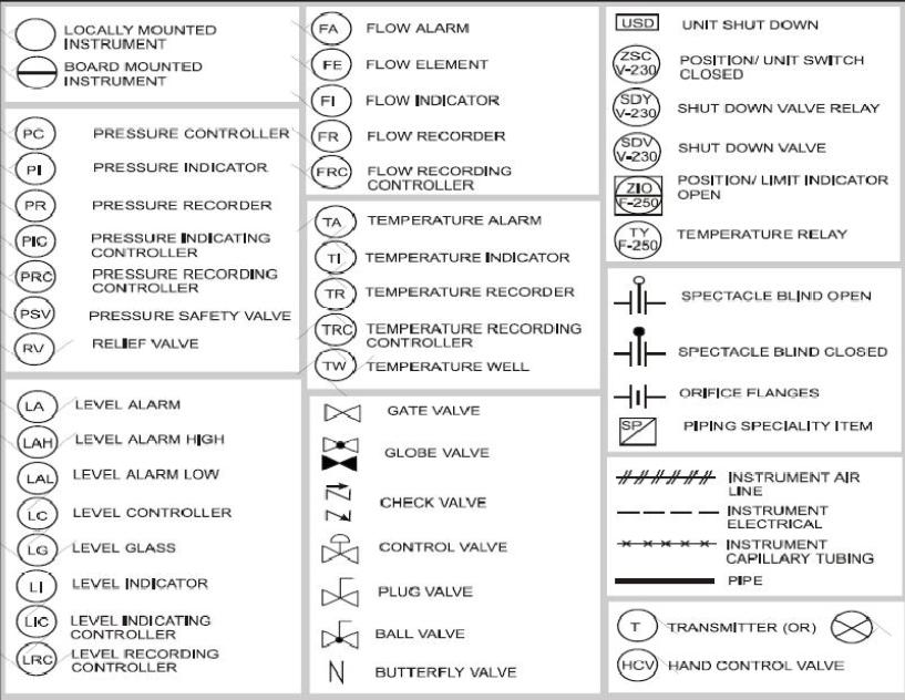
A thermocouple symbol in a P&ID typically consists of a circle with a tag letter indicating the measured variable (T for temperature) and a unique identifier. Additional letters within the circle denote the thermocouple type (e.g., TE for Type E). Lines connecting the circle to the process line represent the thermocouple's physical location and connection.
Benefits of using standardized thermocouple symbols:
1. Improved Communication: Standardized symbols eliminate ambiguity and facilitate clear communication among engineers, operators, and technicians.
2. Reduced Errors: Accurate and consistent symbology minimizes the risk of misinterpretations, preventing costly errors during design, installation, and maintenance.
3. Enhanced Safety: Clear representation of thermocouple locations and types contributes to safer plant operation by ensuring proper monitoring and control of critical temperatures.
Advantages and Disadvantages of Standardized Thermocouple Symbols
| Advantages | Disadvantages |
|---|---|
| Clear Communication | Requires Training and Familiarization |
| Reduced Errors | Potential for Variations Between Standards |
| Enhanced Safety | Can be Complex for Large P&IDs |
Best Practices for Implementing Thermocouple Symbols in P&IDs:
1. Adhere to ISA-5.1 or other recognized standards.
2. Provide clear and concise instrument tagging.
3. Use consistent symbology throughout the P&ID.
4. Ensure proper documentation of any deviations from standard practice.
5. Regularly review and update P&IDs to reflect changes in the process.
Frequently Asked Questions:
1. What does the letter 'T' inside a circle represent in a P&ID? - Temperature measurement.
2. What do the letters 'TC' denote? - Thermocouple.
3. Where can I find information on standardized thermocouple symbols? - ISA-5.1.
4. Why is accurate thermocouple representation important? - For process safety and efficiency.
5. What are the different types of thermocouples used in industry? - J, K, T, E, R, S, B, N, etc.
6. How are thermocouples depicted in a distributed control system (DCS)? - Often using similar tag naming conventions as the P&ID.
7. What is the difference between a thermocouple and an RTD in a P&ID? - Different symbols and tag letters are used.
8. How can I learn more about P&ID interpretation? - Various training courses and online resources are available.
Tips and Tricks:
Use software tools for creating and managing P&IDs to ensure consistency and accuracy in thermocouple symbol representation.
In conclusion, understanding and correctly applying thermocouple symbols in P&IDs is crucial for effective process control, plant safety, and efficient communication within industrial settings. By adhering to industry standards like ISA-5.1, engineers and operators can ensure clarity and minimize the risk of misinterpretations. The proper use of these symbols facilitates streamlined operations, contributes to a safer work environment, and ultimately optimizes plant performance. Embrace the power of these small but mighty symbols to unlock the full potential of your P&IDs and take your process control to the next level. This meticulous attention to detail, from the seemingly insignificant symbol to the complex process it represents, is the cornerstone of a robust and efficient industrial operation. So, take the time to master the language of P&IDs – it’s an investment that pays dividends in safety, efficiency, and overall plant performance.
Transform your home with sherwin williams interior paint colors
Sherwin williams paint prices 5 gallons your guide to budgeting
Unlocking target with your ebt card online a comprehensive guide


.png)


.png)


