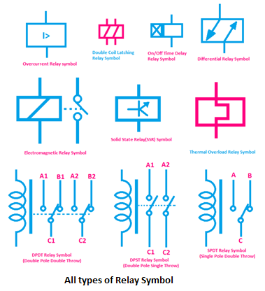
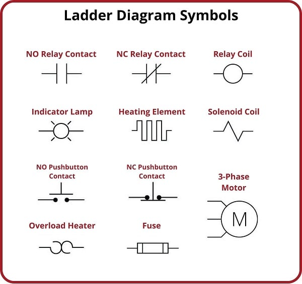
Decoding Electronic Timer Relay Symbols: Your Ultimate Guide

Ever stared at a circuit diagram and felt bewildered by a cryptic symbol resembling a clock with some extra lines and squiggles? Chances are you’ve encountered an electronic timer relay symbol. These seemingly small glyphs hold the key to understanding automated timing control in various electrical systems. This guide will demystify electronic timer relay symbols, providing a comprehensive overview of their significance and application.
Timer relays are fundamental components in countless applications, from simple household appliances to complex industrial machinery. They are essentially automated switches that control the flow of electricity based on pre-set time intervals. Understanding the symbols used to represent them on diagrams is crucial for anyone working with electrical circuits, whether you're a seasoned engineer or a DIY enthusiast.
The symbols for timer relays, while seemingly complex at first glance, are standardized to ensure clear communication across different disciplines and regions. These standardized representations provide a concise visual language that simplifies complex circuit designs and facilitates troubleshooting. Knowing how to interpret these symbols unlocks the ability to analyze and understand the timing logic within a circuit.
Electronic timer relays come in various types, each tailored to specific applications. From simple on-delay timers that activate a circuit after a specified time to more complex off-delay or interval timers, each type has its unique symbolic representation. Learning to differentiate between these symbols allows for accurate circuit analysis and informed component selection.
The journey into the world of timer relays begins with understanding the basic elements within their symbols. These include contacts, coils, and timing mechanisms, each represented by specific graphical elements. By understanding the individual components and their symbolic representations, you can piece together the overall function of the timer relay within a circuit.
While the exact origins of timer relay symbology are difficult to pinpoint, they've evolved alongside electrical engineering itself, mirroring the development of standardized technical drawing practices. The need for a universally understood visual language led to the creation of these simplified representations. Their importance lies in facilitating clear communication and collaboration amongst engineers and technicians.
A significant issue related to electronic timer relay symbols is the potential for misinterpretation due to regional variations or outdated documentation. Adhering to current industry standards and consulting reliable resources is crucial for avoiding such pitfalls.
For example, an on-delay timer relay symbol might show a normally open contact with an arrow pointing towards it, indicating that the contact closes after a set time. Conversely, an off-delay timer relay might show a normally closed contact with an arrow pointing away, meaning the contact opens after a delay.
Benefits of using timer relays include increased automation, improved process efficiency, and enhanced safety features. For instance, a timer relay can automatically shut off a motor after a specific operating time, preventing overheating and extending its lifespan. In safety systems, timer relays can be used to trigger alarms or shut down equipment in case of malfunctions.
When incorporating electronic timer relays into your circuits, ensure you understand the specifications of the specific relay you're using. Consult the datasheet and wiring diagrams carefully to avoid misconnections or improper configuration. Always test the circuit thoroughly after implementation to verify correct operation.
Advantages and Disadvantages of Electronic Timer Relays
| Advantages | Disadvantages |
|---|---|
| Increased Automation | Potential Complexity in Configuration |
| Improved Process Efficiency | Can be Affected by Environmental Factors (Temperature, Humidity) |
| Enhanced Safety Features | Requires Careful Selection Based on Application Requirements |
Best Practices:
1. Consult Datasheets: Always refer to the manufacturer's datasheet for specific symbol interpretations and operating parameters.
2. Use Standard Symbols: Adhere to established industry standards for consistent communication.
3. Label Clearly: Annotate diagrams with clear descriptions of timer relay functions and settings.
4. Test Thoroughly: Verify circuit operation after implementation to ensure correct timing and functionality.
5. Consider Environmental Factors: Account for factors like temperature and humidity that might affect relay performance.
Examples of electronic timer relay applications include controlling lighting systems in buildings, managing irrigation cycles in agriculture, and regulating the operation of industrial machinery. Challenges can arise from incorrect wiring, improper voltage supply, or environmental interference. These can be addressed by careful circuit design, proper component selection, and robust troubleshooting techniques.
FAQs:
1. What is an electronic timer relay? - An electronic device that controls a circuit based on a pre-set time.
2. What are the different types of timer relays? - On-delay, off-delay, interval timers, etc.
3. How do I read a timer relay symbol? - Consult datasheets and industry standards.
4. What are the common applications of timer relays? - Industrial automation, building control, appliances.
5. How do I choose the right timer relay? - Consider the application requirements and relay specifications.
6. How do I troubleshoot a timer relay circuit? - Check wiring, voltage supply, and relay settings.
7. Where can I find more information on timer relay symbols? - Manufacturer datasheets, industry standards documents, online tutorials.
8. What are some safety precautions when working with timer relays? - Ensure proper wiring and voltage levels to prevent electrical hazards.
Tips and tricks: Use simulation software to test your circuit designs before implementation. Invest in a good multimeter for accurate voltage and current measurements during troubleshooting.
In conclusion, understanding electronic timer relay symbols is paramount for anyone working with electrical circuits. These compact graphical representations encapsulate a wealth of information about the timing logic within a system. By mastering the art of interpreting these symbols, you unlock the ability to design, analyze, and troubleshoot circuits with confidence. From automating simple tasks to enhancing complex industrial processes, timer relays play a vital role in modern technology. By learning about their symbols, functionality, and applications, you gain valuable tools for creating efficient, reliable, and safe electrical systems. Embrace the power of timing control and unlock the potential of automated systems through the understanding of these seemingly small, but incredibly powerful symbols. This knowledge is not just for professionals but also empowers hobbyists and DIY enthusiasts to engage with electronics on a deeper level, opening doors to creativity and innovation. So, delve into the world of electronic timer relay symbols, and you'll find yourself equipped to tackle a wide range of electrical projects with confidence and precision.
Illinois property tax rollercoaster decoding the circuit breaker
Finding your perfect pre owned rav4 in victoria
Unlocking the potential of benjamin moore blue paint colors


