Decoding Relay Symbols Circuit Speak

Ever peered at a circuit diagram and felt lost in a maze of squiggles and lines? You're not alone. Understanding the language of electronics, especially the cryptic shorthand of schematic symbols, can be daunting. One particularly important symbol, the relay's graphical representation, acts as a gateway to understanding how many circuits control larger loads.
Relays are electromechanical switches, miniature marvels that allow a small current to control a much larger one. Imagine a light switch for a powerful floodlight; that’s the relay's role in a nutshell. Their schematic symbol, however, takes several forms depending on the relay type, adding a layer of complexity to circuit analysis.
The graphical representation of a relay on a schematic diagram is more than just a simple icon. It's a visual key unlocking the functionality and connections within a circuit. By understanding the nuanced differences in relay symbols, we can decipher the intricacies of a circuit’s design and purpose.
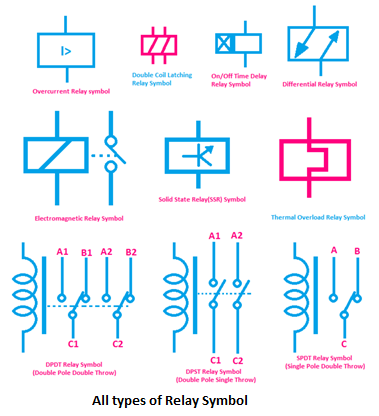
The evolution of the relay symbol mirrors the development of electrical engineering itself. Early diagrams relied on simplistic depictions, evolving over time to reflect the increasing complexity of relay designs. From basic single-pole single-throw (SPST) relays to more intricate latching and multi-pole configurations, the symbol has adapted to encompass the broader range of relay types and functions.
Relay schematic representations play a crucial role in modern circuit design. They provide a standardized visual language that transcends geographical and linguistic barriers, allowing engineers worldwide to collaborate and share their creations. Misinterpreting these symbols, however, can lead to circuit malfunctions, highlighting the importance of accurate and standardized relay symbol usage.
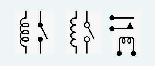
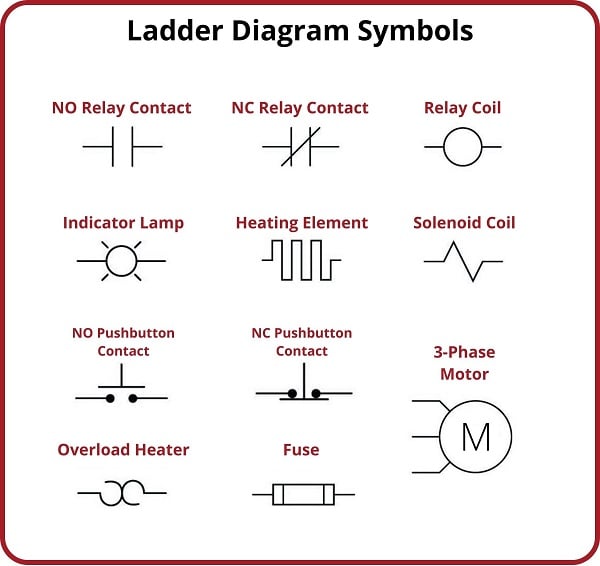
A typical relay diagram depiction involves a coil and a set of contacts. The coil, often represented as a rectangle or circle with connected leads, is the electromagnet that activates the relay. The contacts, depicted as lines connected to terminals, are the switches controlled by the coil's magnetic field. A simple example is an SPST relay symbol, showing one set of normally open contacts that close when the coil is energized.
Understanding the specific features within a relay graphical representation provides invaluable insights into its operation. Recognizing different contact arrangements, such as normally open (NO) or normally closed (NC) contacts, is fundamental. Furthermore, identifying specialized relay types like latching or time-delay relays by their unique symbols allows for a more comprehensive circuit analysis.
One benefit of standardized relay graphics is clarity. They provide a concise and universally recognized way to represent these components in complex circuits, eliminating potential ambiguity. Secondly, standardized symbols facilitate circuit design and simulation. Software tools utilize these symbols for creating and analyzing circuits, streamlining the design process. Lastly, proper use of relay symbols enhances troubleshooting. By quickly identifying relay types and their connections, technicians can diagnose and resolve circuit issues more efficiently.
Advantages and Disadvantages of Standardized Relay Symbols
| Advantages | Disadvantages |
|---|---|
| Clarity and universal understanding | Potential for confusion with similar symbols |
| Facilitates circuit design and simulation | Requires knowledge of different relay types and their corresponding symbols |
| Enhances troubleshooting and maintenance | Variations in symbol representation across different software or standards |
Best Practices for Implementing Relay Symbols:
1. Adhere to established standards (e.g., IEC, ANSI) to ensure consistency.
2. Clearly label all relay contacts and coil connections to avoid confusion.
3. Indicate the relay type (e.g., SPST, DPDT) near the symbol for quick identification.
4. Use consistent line weights and spacing for a professional and readable schematic.
5. Double-check all relay symbols and connections before finalizing the circuit design.
Frequently Asked Questions:
1. What is the basic symbol for a relay? Answer: It typically consists of a coil and a set of contacts.
2. How do I differentiate between NO and NC contacts in a relay symbol? Answer: NO contacts are shown open, while NC contacts are shown closed in the de-energized state.
3. What does a latching relay symbol look like? Answer: It usually includes an additional indicator to signify its latching function.
4. Where can I find reliable resources for relay symbols? Answer: Refer to industry standards like IEC or ANSI.
5. Why is it important to use standardized relay symbols? Answer: It promotes clarity and understanding among engineers and technicians.
6. Are there different relay symbol standards? Answer: Yes, different standards exist, but they share common core elements.
7. How can I improve my understanding of relay symbols? Answer: Practice reading and interpreting circuit diagrams that include relays.
8. What software tools can help with relay symbol implementation? Answer: Many CAD and circuit simulation programs offer libraries of standard relay symbols.
Tips and Tricks: When working with complex circuits, creating a separate relay legend can be beneficial. This legend clearly defines each relay symbol and its corresponding function within the circuit, reducing the risk of misinterpretation.
In conclusion, the seemingly simple relay schematic symbol holds profound significance in the world of electronics. Understanding its nuances empowers us to dissect circuit diagrams, unravel their functionality, and appreciate the ingenuity behind their design. Mastering the language of relay symbols is not just about reading a schematic; it's about unlocking the secrets of electrical control systems and harnessing the power of these miniature electromechanical marvels. From simple household appliances to complex industrial automation, relays play a vital role in our technology-driven world. By embracing standardized practices and continually expanding our knowledge of relay symbols, we can ensure clear communication, efficient design, and reliable troubleshooting in the realm of electronics. Take the time to familiarize yourself with the diverse world of relay representations – the knowledge gained will undoubtedly pay dividends in your electrical endeavors, whether you're a seasoned engineer or a curious beginner. Dive deeper into the intricacies of relay symbols and unlock a whole new level of understanding in the world of circuit design and analysis.
Unlocking the mystery of duke dennis purple cologne
Decoding the chevy 2500 bolt pattern your ultimate guide
Master your car ac the ultimate guide to auto ac vacuum pump kits


