Unlocking Electronics: A Guide to Circuit Diagram Symbols

Imagine trying to build a complex structure without blueprints. In the world of electronics, circuit diagrams and their symbols serve as these crucial blueprints. They are the universal language that allows engineers and hobbyists alike to design, analyze, and troubleshoot electronic circuits. Without a solid understanding of these symbolic representations, navigating the fascinating world of electronics becomes an almost impossible task.
Electronic circuit diagrams are graphical representations of electrical connections and components. They depict the flow of electrical current and the relationships between different components. At the heart of these diagrams are standardized symbols, each representing a specific electronic component or function. From resistors and capacitors to transistors and integrated circuits, each symbol conveys essential information about the component's role within the circuit.
The history of electronic circuit diagram symbols is intertwined with the development of electronics itself. As electronic circuits became more complex, the need for a standardized symbolic representation arose. Early diagrams were often crude and varied, leading to confusion and misinterpretations. Over time, organizations like the Institute of Electrical and Electronics Engineers (IEEE) and the International Electrotechnical Commission (IEC) developed standardized symbols, ensuring clarity and consistency across the globe. These standardized representations are vital for effective communication and collaboration within the electronics community.
The importance of understanding electronic circuit symbols cannot be overstated. These symbols are the building blocks of circuit design. They allow engineers to communicate complex circuit designs efficiently, enabling collaboration and innovation. Furthermore, these symbols are essential for troubleshooting faulty circuits. By analyzing the symbols and their connections, technicians can quickly identify and rectify problems.
One of the main issues related to electronic circuit diagram symbols is keeping up with the ever-evolving technology. As new components are developed, new symbols need to be introduced and standardized. This requires continuous updates and revisions to ensure that the symbols remain relevant and universally understood. Another challenge lies in interpreting complex diagrams with a multitude of components and connections. Mastering the art of reading and understanding these intricate diagrams requires practice and a deep understanding of the underlying electronic principles.
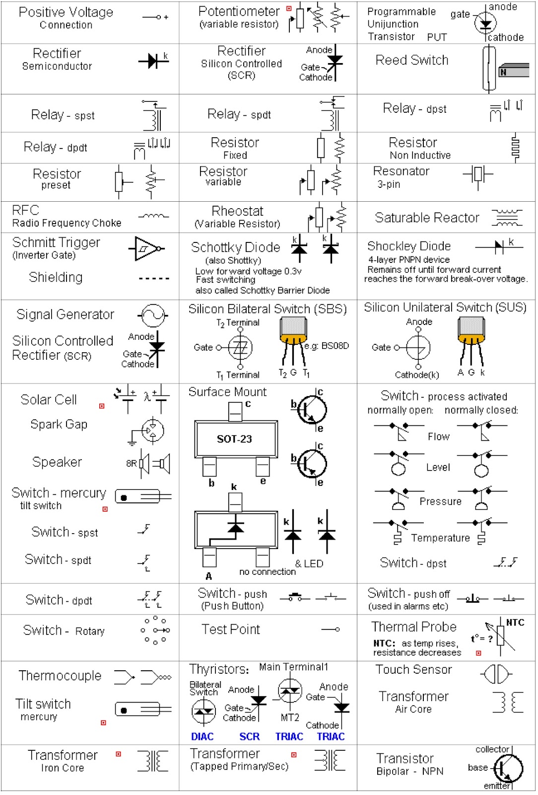
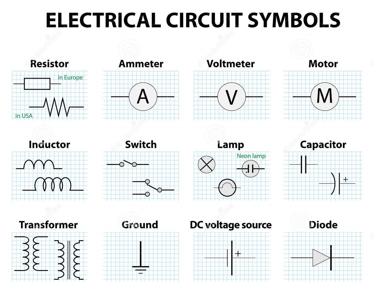
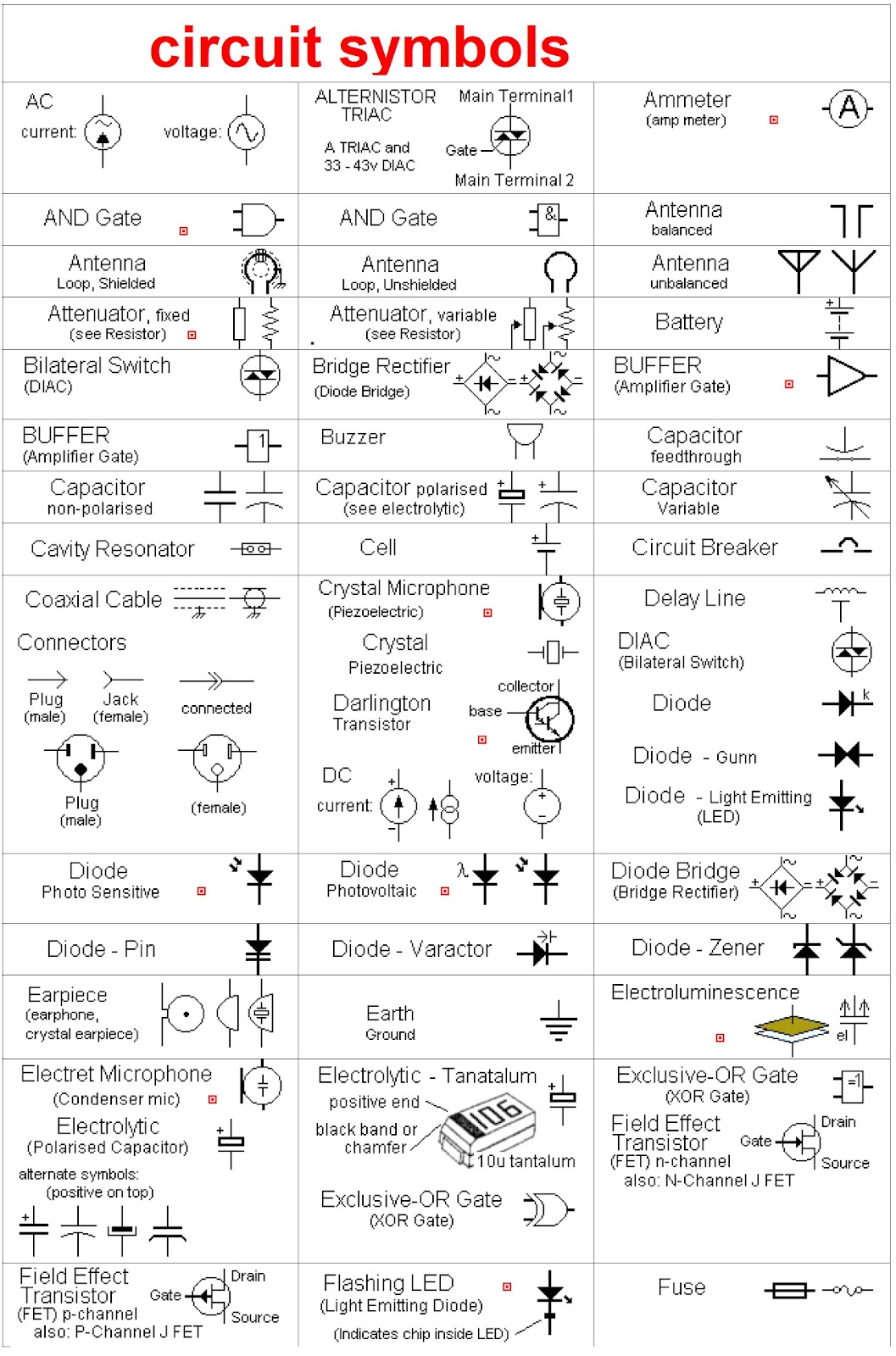
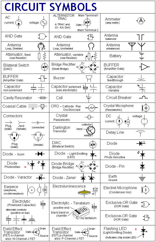
A resistor, for example, is represented by a zigzag line, while a capacitor is depicted by two parallel lines. These simple yet powerful symbols allow engineers to quickly grasp the function and purpose of each component within the overall circuit.
Benefits of using standardized electronic circuit symbols include: 1) Clear and concise communication: Symbols eliminate ambiguity and ensure that everyone involved understands the circuit design. 2) Easier troubleshooting: Symbols facilitate the identification of faulty components and connections. 3) Simplified design process: Symbols allow engineers to quickly visualize and design complex circuits.
To learn electronic circuit symbols effectively, start with the basic components like resistors, capacitors, and inductors. Practice drawing simple circuits and gradually increase the complexity. Use online resources and textbooks to expand your knowledge and familiarize yourself with a wide range of symbols.
Advantages and Disadvantages of Standardized Symbols
| Advantages | Disadvantages |
|---|---|
| Universal understanding | Can be complex for beginners |
| Facilitates troubleshooting | Requires continuous learning as new symbols emerge |
| Simplifies complex designs |
Best practices for using electronic circuit symbols include maintaining consistency, using clear labels, and organizing the diagram logically. Always double-check your work to avoid errors.
Real-world examples of circuit diagrams include the schematics for a simple flashlight, a radio receiver, or a computer motherboard.
Common challenges include understanding complex diagrams and keeping up with new symbols. Solutions include practicing reading diagrams regularly and consulting online resources.
FAQs: What is a resistor symbol? What does a diode symbol look like? What are the common symbols used in digital circuits? How do I interpret a complex circuit diagram? Where can I find a comprehensive list of electronic symbols? What is the difference between a schematic diagram and a wiring diagram? What software can I use to draw circuit diagrams? How do I learn more about electronic circuit design?
Tips and tricks for working with electronic circuit diagram symbols include using software tools for creating and simulating circuits, referencing online libraries of symbols, and joining online communities to learn from experienced engineers.
In conclusion, electronic circuit diagram symbols are the essential language of electronics. They provide a standardized way to represent complex electrical systems, facilitating design, analysis, and troubleshooting. While learning all the symbols can seem daunting initially, the benefits of mastering this visual language are immense. By understanding and utilizing these symbols effectively, you unlock the power to design and understand the electronic devices that shape our modern world. Take the time to learn these symbols; it’s an investment that will pay off in countless ways as you explore the exciting field of electronics.
Unlocking medicare part b coverage your guide to supplemental insurance
Score big exploring fifa 23 for windows 10
Unlocking the allure of benjamin moore gold mine


