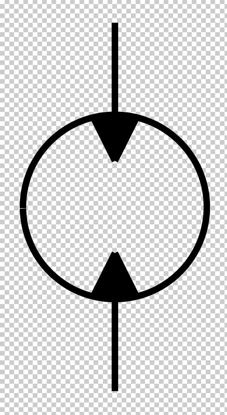
Unlocking Power: Hydraulic Pump and Motor Symbol Explained

Ever wondered about the cryptic diagrams that grace hydraulic system blueprints? Those seemingly simple symbols hold the key to understanding how power is transmitted and harnessed in countless applications, from construction equipment to aircraft control systems. One crucial symbol, often overlooked, is the representation of a hydraulic pump coupled with a motor. Decoding this symbol unlocks a world of information about the system's function and capabilities.
The hydraulic pump and motor symbol visually represents the heart of a hydraulic system. It depicts the power source (the pump) that generates hydraulic flow and the actuator (the motor) that converts this flow back into mechanical power. Understanding this symbol is essential for anyone working with or designing hydraulic systems. It allows for quick interpretation of circuit diagrams and aids in troubleshooting and maintenance.
The combined pump-motor symbol has evolved alongside hydraulic technology. Early representations were simple, but as systems grew in complexity, the symbol became more detailed, often incorporating information about pump type, motor displacement, and control mechanisms. This evolution reflects the increasing sophistication of hydraulic systems and their integration into more advanced machinery.
The significance of the hydraulic pump with motor symbol lies in its ability to convey crucial information about the system's power transmission capabilities. The symbol often includes details about the pump's flow rate and the motor's torque output, allowing engineers to quickly assess the system's performance potential. This information is vital for selecting appropriate components and ensuring optimal system efficiency.
Several factors can influence the representation of a hydraulic pump motor unit. These factors include the specific type of pump and motor used (e.g., gear pump, vane pump, piston pump, etc.), the presence of control valves or other components within the combined unit, and the overall complexity of the hydraulic circuit. This variability emphasizes the need for a thorough understanding of hydraulic symbols and their interpretations.
The history of hydraulics dates back to ancient times, but the modern hydraulic pump and motor symbol emerged with the development of standardized schematic diagrams for hydraulic systems. These standardized symbols allow for clear and concise communication between engineers and technicians, regardless of language barriers.
One simple example of a hydraulic pump with motor application is a forklift. The pump, powered by the engine, generates hydraulic fluid flow, which drives the motor connected to the lifting mechanism. This enables the forklift to lift heavy loads efficiently. Another example is a backhoe loader, where a pump supplies pressurized fluid to multiple motors, enabling the operation of the boom, bucket, and other components.
A key benefit of using a combined hydraulic pump and motor system is its compact size and efficiency. Integrating the pump and motor into a single unit reduces space requirements and minimizes piping complexity. This streamlined design enhances overall system performance.
Another advantage is the ability to precisely control the speed and torque of the motor by regulating the flow of hydraulic fluid from the pump. This fine-tuned control is essential in applications requiring precise movements, such as robotic arms and industrial machinery.
Finally, hydraulic systems offer high power density, meaning they can deliver significant power in a relatively small package. This characteristic makes them ideal for applications where space and weight are limited, such as in aircraft and mobile equipment.
Advantages and Disadvantages of Hydraulic Pump with Motor Units
| Advantages | Disadvantages |
|---|---|
| Compact Size | Potential for leaks |
| High Power Density | Noise generation |
| Precise Control | Maintenance requirements |
One real-world example of a hydraulic pump-motor unit is in a hydraulic press. The pump generates high-pressure fluid to drive a motor connected to the press ram, enabling the application of significant force for shaping metal or other materials. Another example is the hydraulic system in an excavator, where the pump supplies fluid to motors controlling the boom, arm, and bucket, allowing for precise digging and material handling.
A common challenge in hydraulic systems is contamination of the hydraulic fluid. Implementing proper filtration and fluid maintenance procedures is crucial to prevent damage to the pump and motor and ensure system longevity.
FAQ 1: What is the difference between a hydraulic pump and a hydraulic motor? Answer: A hydraulic pump converts mechanical energy into hydraulic energy (flow and pressure), while a hydraulic motor converts hydraulic energy back into mechanical energy (rotation or linear motion).
FAQ 2: What are the different types of hydraulic pumps? Answer: Common types include gear pumps, vane pumps, and piston pumps.
In conclusion, understanding the hydraulic pump with motor symbol is fundamental for anyone involved with hydraulic systems. From its historical significance to its modern-day applications, the symbol represents a core concept in fluid power transmission. By mastering the interpretation of this symbol, engineers and technicians can effectively design, maintain, and troubleshoot hydraulic systems, harnessing their power and versatility for countless applications. Take the time to delve deeper into the world of hydraulics, and you’ll unlock a wealth of knowledge about this powerful technology.
Unleash the pitch your ea sports fc 24 playstation store guide
Illuminating upgrades your guide to ceiling light transformer replacement
Chevy volt lug nut torque your guide to proper wheel fastening


